I was very busy during the last two months so, as a result, I had little to no time to write something.
Something interesting at least…
During some spare time of the last week, I built a really simple and cheap headphone amplifier. I needed one because sometimes I like to listen to some sat radio station (especially for news) and I don’t want to leave the TV on only to use it as an headphone amplifier.
I wanted to keep the complexity low, really low, so I decided to use a pair of ICs instead of four ( one amplifier and one buffer per channel ) or more transistors.
There are various IC audio amplifiers. Some are huge AB class amplifiers able to deliver dozens of Watt to a 4 Ω load. That is not my case, because headphones usually have an impedance of 16 Ω or more.
The one I selected was the National LM386, a small 8 pin IC in a DIL package.
Considering the low output power, there is no need for a heatsink. Moreover, the air inside the case shouldn’t be hotter than the air outside, despite the little heat generated by the voltage regulator.
Using the LM386, only two external cap per channel are required. Without any further component, it’s easy to obtain a fixed gain of 20.
Talking about the PS (power supply), my idea was to use a cheap wall mount PS but, as many people know, sometimes ( *almost always* ) “cheap” means “unregulated-with-an-output-voltage-completely-different-from-the-rated-one”. Furthermore, a PS like that usually have different type and size of plugs, some with inverted polarity ( many devices use a plug with the negative/ground on the outside ).
So my amplifier needed to have its own voltage regulator and at least a diode to prevent damages in the case I or someone else accidentally connect a PS plug with the wrong polarity.
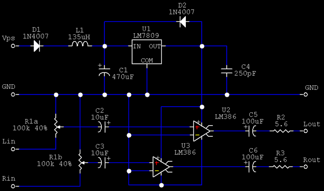
- Vps ( and GND of course ) must be connected to a PS with a minimum rated output of 12 V;
- D1 could be any 1 A diode, same for D2. 1N4001, 1N4002, etc are perfects;
- L1 is not essential. Without it I hear a stronger 100Hz noise, depends by your PS;
- C1 could be smaller or bigger, again depends by your PS;
- U1 is the standard LM7809 3 pin fixed voltage regulator in the TO220 package. A very small heatsink is ok;
- The value of C4 is not critical, but should be mounted close to U2 and U3;
- Lin and Rin are the two audio input from RCA plugs;
- R1a and R1b are two halfs of the double 100 kΩ potentiometer R1. R1 should be logaritmic;
- C2 and C3 could be smaller (but equals);
- About C5 and C6, the larger, the better;
- R2 and R3 must be equals and not bigger than 8 Ω;
- Lout and Rout are the output to the jack plug.
Now some technical details:
- Vps must be greater or equal to 12 V and lower than 35 V. Assuming a 2V drop on U1 and a 0.7 V drop on D1, this lead to a minimum Vps of 11.7 V. As Vps raises, so do the temperature of U1 so be careful about heat generation;
- The input impedance of the LM386 is 50 kΩ, so the value of C2 and C3 can affect the bandwidth. Keep in mind that usually there is also a cap on the output stage of the audio source, so actually there are two caps in series: the total capacitance is smaller than that of the smallest cap;
- If you want to add a LED, simply connect it in series with a 1 kΩ resistor between the output of U1 and GND;
- R2 and R3 are sorta short circuit protection;
- There isn’t a Zobel network in this project. If you think you need one ( e.g. the amplifier oscillate ), add a 10 Ω resistor in series with a 50 nF cap between the outputs ( before R2 / R3 ) and GND.
I have used many spare parts to build this amplifier, but I think that 15 € should be enough to buy all the components.
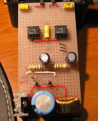
Some spaces I left on the board are needed because of the various connectors that are very close to the board itself.
I used a 0.5 mm solder wire and I made most of the link on the copper side of the board.
I used a plastic enclosure, but if you plan to use a metallic one, beware of ground loops and remember to insulate any plug from the enclosure chassis.
Could be a nice project if you are relatively new in building electronic circuit, but I don’t suggest it as the first circuit to build, because doing problem solving on audio circuit could be really frustrating.
The result (mine) is this, black and only a bit greater than a mouse.
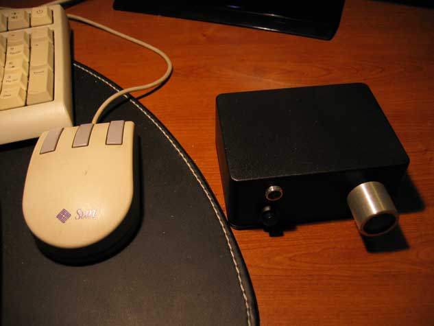
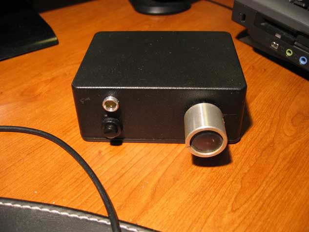
The front side of the amplifier with the power LED, power switch and the volume knob.
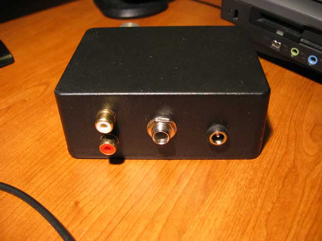
The rear side of the amplifier with the RCA plugs, 6.3mm jack plug and the PS plug.
Bye
No Comments