Archive for the ‘hardware’ Category


Because, even with Q-Fan enabled for the chassis fans and put on “silent” in the BIOS, they’re pretty loud, especially if like me you’re still using a mix of 80, 92 and 120 mm fans.

This guide has been written on Linux Mint 20, and is specifically for the Asus P6T Deluxe V2 motherboard. I hope the revision doesn’t matter. In case it does, I’m sorry: you’re out of luck.
Information here could apply to other Asus motherboards, but I’ve still not done other tests.

Of course, the obvious disclaimer: the following procedure is provided as-is.
My computer is still up and running (quieter than before), but if your CPU fan stops spinning, your computer catches fire, there is some fuel around it, and it starts a chain of event that leads to the core of the nearest nuclear power plant melting down, I’ll have nothing to do about it.

Ok, so, first thing firsts: the ASUS P6T Deluxe V2 is a twelve years old motherboard but because it can use cheap 6-core / 12-threads LGA-1366 Xeons, available for as low as 15-20$ on AliExpress, is still hard to find and the prices are still high. Also, it’s a good platform for overclocking and it’s not that difficult to run a 2.5/2.6 GHz 6C Xeon at 3.5/3.8GHz stable. Extreme overclocking can lead top-tier Xeons up to 4.2 or even 4.5 GHz.
Thus, this motherboard is not cheap on the used market.
It just happens that I bought one new in 2010, along with an i7-930 – a 1st gen Core i7 from Intel – that I replaced for an X5650 and then for an X5660, currently on the board, but not overclocked (anymore). The case I used back then is the same as now, a Chieftec Dragon, which by today standard is a pretty old design.

Let’s get to fan speed.

This motherboard has 5 fan headers in total: 1 4-wire (PWM) for the CPU, 3 3-wire for the case fans and 1 3-wire for the PSU fan (whose speed cannot be adjusted).

I currently have four chassis fan connected to the system, all by Arctic Cooling: a front intake 80mm F8, a pair of intake 92mm F9 on the side panel (using a fan cable splitter) and a rear exhaust 120mm F12. None of these are PWM, they’re regular 3-pin fans.
The fan are connected as follows:
front F8 → CHA_FAN1 header
side F9s → CHA_FAN3 header
rear F12 → CHA_FAN2 header

The fan speed can be adjusted by the BIOS or the Operating System
* BIOS: This motherboard support the so-called Q-Fan feature on both the CPU and the chassis fan, and I’ve enabled it, using the “Silent” profile.
* OS: Under Windows there is the well-known ASUS Fan Xpert tool (but I suppose SpeedFan would have worked as well).

With the BIOS control, in silent mode, fan are quieter… but not so much. Both the front and side fans were spinning at around 1300 rpm even with the CPU completely idle at 30°C.

Under windows, with Fan Xpert, I was able to further reduce the fan speed to around 700/800 rpm at idle.

Under Linux… well there are quite a few problems to solve.

The first one is the ASUS ATK0110 driver. As much as I like ASUS motheboards, I’ve never – ever – understood the purpose of this driver.

Mint is “smart” enough to load this driver – asus_atk0110 – automatically so with the use of the lm-sensors package you can have access to temperatures, fan speeds and voltages. Install xsensors and you can even see them in a “nice” GUI application with a “very cool” 1995 feel (all those quotes are there for a reason, you know?).

The only problem is that if you attempt to run pwmconfig to control the fan speed, as reported in many guides, it tells you that there are no pwm-controllable fan in the system (which is kinda true, as the only PWM fan is the cpu one, but I’m not gonna control it, I’ll leave that to the BIOS as it’s not so loud after all). That’s because ATK0110 is something… well… not exactly defined. You find the “same” driver more or less on any ASUS product, from cheap laptops to workstation-grade motherboards, but there are different incarnation of the device and the related driver.

So, thank you Mint for loading the driver automatically, but… let me just use another one.

A quick series of “apt install”s, just to be sure everything is installed and up-to-date:

# apt install lm-sensors xsensors fancontrol

Similarly to what I’ve already done by editing a file “by hand” for lm-sensors (you can copy the content of this file and put it in a file like /etc/sensors.d/ASUS-P6T-Deluxe-V2):

# libsensors configuration file for ASUS P6T Deluxe V2
# ----------------------------------------------------

chip "w83667hg-*"

label in0 "Vcore Voltage"
label in3 "+3.3 Voltage"
label in2 "AVCC"
label in7 "3VSB"
# label in8 "Vbat"

set in2_min 3.3 * 0.90
set in2_max 3.3 * 1.10
set in3_min 3.3 * 0.90
set in3_max 3.3 * 1.10
set in7_min 3.3 * 0.90
set in7_max 3.3 * 1.10
set in8_min 3.0 * 0.90
set in8_max 3.3 * 1.10

label fan1 "CHASSIS1 FAN Speed"
label fan2 "CPU FAN Speed"
label fan3 "POWER FAN Speed"
label fan4 "CHASSIS2 FAN Speed"
label fan5 "CHASSIS3 FAN Speed"

label temp1 "MB Temperature"
ignore in8

After a quick check to be sure the correct driver has been loaded:

# lsmod | grep w83627
w83627ehf 49152 0
hwmon_vid 16384 1 w83627ehf

After running pwmconfig, you can customize the /etc/fancontrol file as follow:

# Configuration file generated by pwmconfig, changes will be lost
INTERVAL=10
DEVPATH=hwmon2=devices/platform/w83627ehf.656 hwmon3=devices/platform/coretemp.0
DEVNAME=hwmon2=w83667hg hwmon3=coretemp
FCTEMPS=hwmon2/device/pwm2=hwmon3/temp2_input
FCFANS= hwmon2/device/pwm2=hwmon2/device/fan1_input
MINTEMP=hwmon2/device/pwm2=35
MAXTEMP=hwmon2/device/pwm2=75
MINSTART=hwmon2/device/pwm2=80
MINSTOP=hwmon2/device/pwm2=75
MINPWM=hwmon2/device/pwm2=75
MAXPWM=hwmon2/device/pwm2=235

The result I obtained is the following (just ignore the ‘qlcnic’ temperature sensors of the network card):

And now the system is so much quiter (not silent, as it wasn’t my original purpose) than before that it’s reasonable to work on it.
This blog post was written on the PC in question after all.

Bye
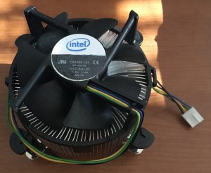


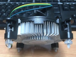
Just kidding of course, but I’m always puzzled by all the type of Intel’s stock coolers existing today.

Numbers doesn’t help much as they’re not used to code the type, features, etc. of the heatsinks.

So here they are…

(This is a continuos work-in-progress blog post: bear with it)

Unless otherwise specified, they’re all equipped with a 4 wire, 12Volt, PWM fan.

D34017-002: TBA

D34223-001: TBA

D60188-001: Your stock “Full-Height” LGA775 copper-core heatsink with a Delta fan (mine came with a Core 2 Duo E6600)

D95263-001: TBA

E18764-001: According to this Phoronix Review, this should be the stock “Low-Height” copper-core heatsink of the Core 2 Duo e8400.

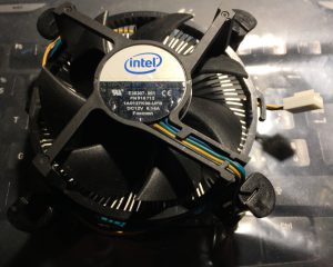
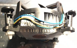
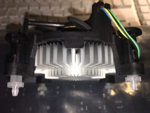
E29477-002: Your stock “Full-Height” LGA1366 copper-core heatsink with a Foxconn fan (mine came with an i7-930)

E30206-001: TBA

E30307-001: Your stock “Low-Height” LGA775 copper core heatsink with a Foxconn fan (bought mine used… don’t know with which CPU was bundled)

E33681-001: TBA

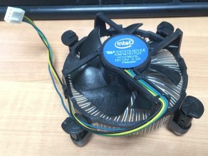
E97379-003: have fun! This is a “Low-Height” LGA1150/1/5/6 all-aluminum heatsink with a Foxconn or Nidec fan
I have two of those: one came with an i3-6100, another with an i5-7500. Same number but slightly different heatsinks.


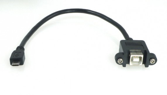
With the arrival from Hong Kong of the last adapter, I was finally able to finish my upgrade!

USB B panel mount connector

USB B panel mount connector

I enlarged the hole for the original cable and mounted there the panel connector. I can now use whatever USB cable (long or short) I like.

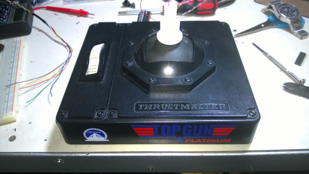
Joystick with USB B port mounted

Joystick with USB B port mounted

In the end, this was, after all, a ‘test project’. I’m not gonna use this joystick a lot because… well, I just bought a Thrustmaster Hotas Warthog, and it’s worth every cent I paid.

In conclusion, what I learned from this project?

  • When ordering more than one piece of electronic from eBay, especially from Hong Kong, it’s better to try everything when the items arrive, not just when one needs them.
  • Without both good gimbals and good springs there is not a good joystick. I did this upgrade because I’m attached to this joystick as it was my first “good” flight controller like 17 years ago and I didn’t want it to stay on the bottom of a box with other useless things. I don’t recommend anyone to buy this joystick with the purpose of upgrading it like I did. Maybe it’s better to buy an FCS Mark II or an X-fighter (better gimbals and better springs if what I read it’s true).
  • Cheap pots are cheap (Department of Redundancy Department here). What I mean is that I opted not to upgrade the pots with newer parts or hall sensors, partly because I’m lazy, partly because I think it was completely pointless (gimbals and springs). This means a lot of “garbage” on the analog inputs. Also, this means that the highest and lowest voltage levels change for various reasons (humidity, heat, planetary alignment…).
  • Flight Simulators are a niche product nowadays but the community is still alive and is doing fine. Cheap $5 Arduino’s clones are extremely versatile. They’re great, really great. Making the electronic parts for a flight controller (sensors excluded) has never been this cheap.
  • MMjoy2 is one hell of a software. It’s incredible, does everything, it’s free and open source (hosted on GitHub). I can’t be more grateful to the developer for making this fantastic work.

In the end,  my next project will be focused on the same upgrade to a Suncom F-15E Raptor joystick I bought used for €20. I’m also currently looking on eBay for old Thrustmaster TQSs (but the Hotas Cougar throttle it’s more appealing).

After all… it was fun. I’m not gonna use it very much, but I’m fine knowing I did this upgrade.


With two axis and one throttle the stick is suitable for a lot of activities (like flying a Cessna, with a set of rudder pedals), but not for military purposes. We need at least a trigger and a weapon release button (the trigger is used only for the gun, while the weapon release button, well release – or drop, or launch, or whatever – the selected weapon, except when the selected weapon is the gun) to use this joystick for combat sim.

Anyway, first things first: MMjoy2 allows two types of button’s connection.

  • Buttons connected via shift registers (any number up to 128 per device or a little less)
  • Buttons connected via button matrix (up to 100 via a 10×10 matrix but with some limitations because of the high number of I/O pins used)

If you want to connect a single button, you have to create a 1×1 matrix (silly concept, I know, but that’s the way it works). MMjoy2 guidelines states that over about 10 buttons, shift registers are the way to go. I agree, maybe not with 10, maybe over 16 I’d go with shift registers too.

Back to the Top Gun Platinum (by the way I’ve seen Top Gun – the movie – in a cinema recently for the 30 years anniversary! In – almost – 3D!), we have 4 buttons and a “China Hat” switch.
Let’s have a look to the “DASH 1” of the McDonnel-Douglas F-4E:

Stick functions from the T.O. 1F-4E-1

Stick functions from the TO 1F-4E-1

So we have the aforementioned trigger [TRG], weapon release button [WPR], an Air-Refueling Disconnect button [ARD] and a nose-wheel steering button [NWS]. Then we have the “China Hat” 4-way switch that is used for pitch and ailerons’ trim control.

In the Top Gun Platinum, as I already wrote in the first post of the serie, the hat switch was connected as an axis. I – more or less – destroyed the PCB under the switch to leave the four push buttons in the hat disconnected. Total numbers of buttons for the new configuration: eight.

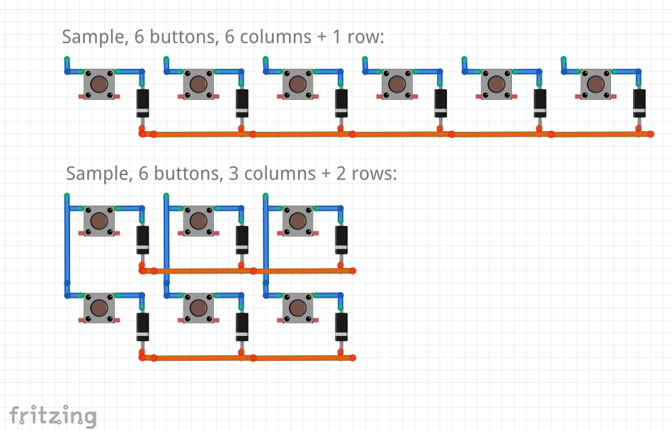
After a quick glance at the MMjoy wiki to check how to connect the buttons in a matrix using as less cables as possible, I decided to go with a 2×4 matrix, 2 rows and 4 columns.

How to connect a button matrix to the MMJoy

How to connect a button matrix to the MMJoy

The diodes are used to prevent ghosting and masking. I found a rather interesting article about those two problems with really simple to understand images. You can read more here [link]. For the diodes, I found eight identical signal diodes. They worked and so I decided to use them. 1N4148s are good to go.

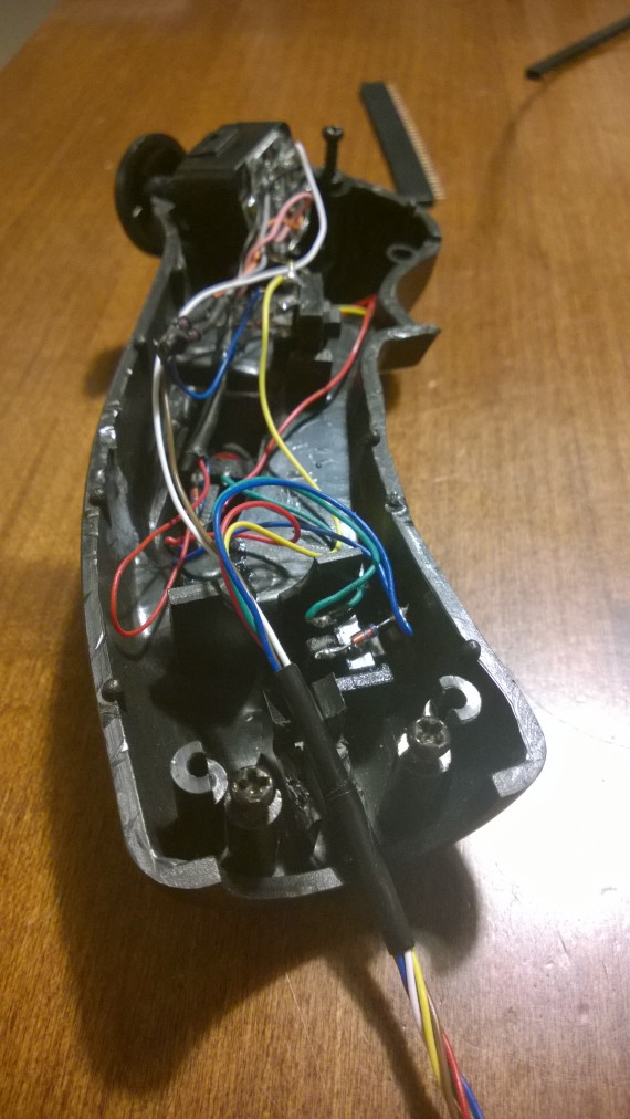
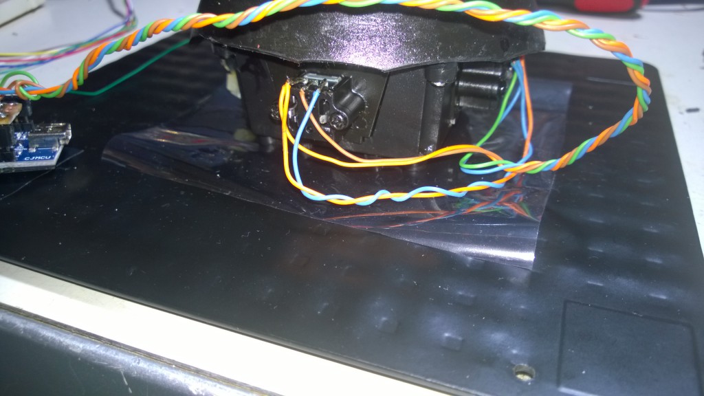
Here is the grip with the new connections:

Inside the grip


wp_20160921_07_21_45_pro Inside the grip

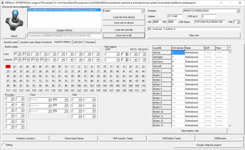
Once the buttons were connected to the Arduino, I started to setup the MMJoy settings for the buttons:

MMJoy setup utility

MMJoy setup utility

The really good thing about MMjoy is that any button in the matrix can be assigned to any button on the device. For instance, I like to assign [TRG] to button 1, [WPR] to button 2, etc. Also, any button can be assigned to the “Hat” up-left-down-right press.

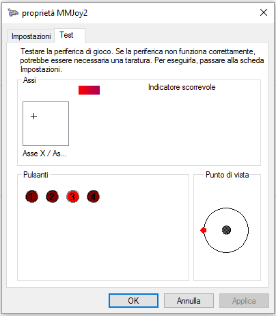
In the end, under Windows, this is a screenshot of the device check screen under Windows 10 control panel:

Windows 10 Joystick Control Panel

Windows 10 Joystick Control Panel

This pretty much sums up almost everything I’ve done. Next and final step will be about the finishing touches (but I’m still waiting for a pair of cables to arrive from Hong Kong).

Bye


With the arrival of two “Pro Micro” Arduinos from an eBay seller in Hong Kong (fast shipping, just two weeks, but one, unfortunately, is not working), work has started on the Top Gun Platinum!
My choice was to use the MMJoy2 firmware that is a really nice software. With MMJoy2 a compatible Arduino is seen as a HID device, so no drivers are needed and compatibility is assured 100% with every software. It’s a really powerful software and I really like it. Links here: MMjoy wiki (en).

Pro Micro Board

Pro Micro Board

The first step (at least for me) was to re-wire the pots (potentiometers) for the two axis and the throttle. The older game port connection worked as an ohm-meter by measuring the resistance of the pots used as variable resistance. The ATMega32U4 integrated ADCs simply read a voltage value between 0 and 5 Volts, from pots, hall sensors, external sources. That means that the pots have to be connected between Ground and 5V (Power or USB +5V) with the cursor connected to one of the ADC pins.

How to connect inputs to the MMJoy2-programmed board

Connecting inputs to the MMJoy2-programmed board

I decided to use wires from a CAT-5 Ethernet Cable for both the axis’ pots and the throttle’s pot.

Axis' pots rewired with wires from CAT 5 cable

Axis’ pots rewired with wires from CAT 5 cable

The throttle's pot with the new wires

The throttle’s pot with the new wires

I also put some grease on the gimbals and on the throttle axis. I used some teflon grease that should last some years (I hope).

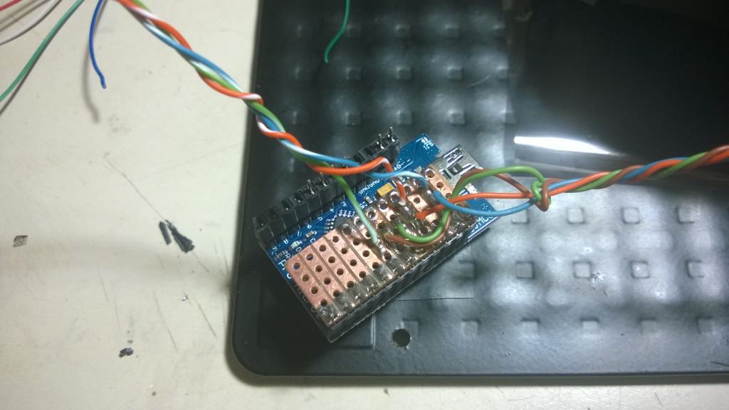
I then connected all the wires to a sort-of “shield” so I can easily swap the board, just in case…

Ghetto shield for axis connection

Ghetto shield for axis connection

Just to make a simple test, I decided to close the base, leaving the board outside.

Board hanging outside the joystick base

Board hanging outside the joystick base

And then a final picture before connecting the base to the PC to test the pots and their connections.

The base closed before a quick test

The base closed before a quick test

The quick test went fine. Next part will be about connecting the grip’s buttons and China HAT (POV) switch.

Bye


(Part 1 of X as, honestly, I have absolutely no idea of how many parts this series of articles will last, anyway).
Oct. 1, 2016 update: Part 1 of 4 😉

If you’re reading this you probably know which company Thrustmaster is, what’s its main business and what are their most known products. Probably you’re a simmer.

If you’re not a simmer, that means a person which is interested in simulation (usually flight simulation), then maybe you don’t know Thrustmaster. This is their website: Thrustmaster.com (US).

Some Thrustmaster products really made history and any good simmer knows them:

  • Pro Flight Control Stick
  • X-Fighter Joystick
  • Rudder Control System
  • Weapons Control System – a programmable throttle controller
  • F-16 TQS and FLCS – full size programmable replicas of the F-16C’s throttle and stick
  • F-22 PRO – a full size programmable replica of the YF-22 stick (almost exactly the same as an F-16C, F-22A’s stick is different)
  • HOTAS Cougar – a renewed F-16’s HOTAS replica controller
  • HOTAS Warthog – a replica of the A-10C’s HOTAS

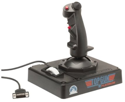
Back on topic, around year 1998/1999 my father bought me a Thrustmaster Top Gun Platinum joystick. The original “Top Gun” (the joystick, not the movie) was an X-Fighter joystick with simpler gimbals and directly attached potentiometers (from now on pots for short). The Top Gun Platinum added a throttle to the base of the controller with an all-black colour style.

Thrustmaster Top Gun Platinum

The joystick we’re talking about

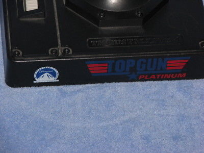
Top Gun and Paramount logos on the joystick

The joystick model with a big logo of Paramount

And now some (interesting?) technical details:

  • The stick is really similar to (but not exactly a replica of) a B-8 grip. The B-8 was a very widespread grip that was used on many US and NATO aircrafts, like the F-4 “Phantom II”, the A-10A “Thunderbolt II”, the Bell 206 “JetRanger III”, the Aermacchi MB-339 and many others.
  • The stick, as usual for that time was connected via game port.
  • It has 3 axis, four buttons and a four way “china hat” switch, usually used in simulators for changing the player’s Point of View (and therefore sometimes named HAT/POV) while in real airplanes is used for pitch and roll trim.
  • Thrustmaster used a “hack” for connecting the hat switch on this and many other joysticks before USB became the standard connection. Because game ports allowed to connect a total of 4 axis and 4 buttons, and the hat switch usually is implemented with 4 microswitches, there was a shortage of buttons that can be connected. Thrustmaster used an axis line and some resistors to send various resistance values to the game port. An “ad-hoc” driver inside the game or the operating system decoded the resistance values and used it as if 4 different buttons were pressed. The drawback is that only “up”, “down”, “left” or “right” directions were allowed (both mechanically and electrically) as it wasn’t possible to combine two commands simultaneously.

Now the project itself is about completely rewiring the joystick and converting it to USB using a cheap Arduino reprogrammed as a HID device.

Part 2 of X will follow when work will actually start.

Bye


A fast update just to say that the adapter is fully working on the Raspberry Pi running NetBSD 6.99.
Connection parameters are 115200-8-N-1 with flow control OFF (ON by default on PuTTY).
The adapter should work also on Rev. 1 Raspberry Pi B models, but there is no P6 (soft reset) header on that revision.

As standalone serial interface, works flawlessly with my old D-Link DSL-G624T wireless modem router. Being a rather old device, it use a slower 38400 bps connection (38400-8-N-1), but, nevertheless, works pretty well.

At last, just to leave no doubts about the SP3232 IC, as mentioned in this article (http://www.fullmeta.it/?p=379):

Sì, sono proprio quelli

Bye


2012 was the year of the Raspberry Pi. This credit card sized computer has become a huge worldwide success.
Running GNU/Linux or other operating systems is an easy task, it just requires to flash an image on an SD Card, put it in the Raspberry and switch on the power supply.

The Raspberry Pi version B sports two USB 2.0 ports (only one on vers. A), a Fast-Ethernet connection (no network on vers. A), HDMI, Composite Video and stereo audio output.
It seems there’s nothing missing on the connection side. You can just plug a TV/monitor, a keyboard (and a mouse) and you’re ready to use the system.
You can also access it via SSH if you’re using Raspian or another OS that automatically enables the network connection and runs sshd or some telnet server at startup.
But, if you don’t have an available TV/monitor and you can’t connect to the Raspberry via network (because there is no DHCP server on your current network or there are no SSH/telnet servers running on the OS), your last chance is a serial console.

I’ll leave the basics to this simple and short article by Joonas Pihlajamaa: http://codeandlife.com/2012/07/01/raspberry-pi-serial-console-with-max3232cpe/
In a nutshell, the Raspberry Pi does have a serial port and a serial console is usually enabled by default by the OS on it, but there isn’t a standard UART/RS-232 connector. Two pins of the GPIO header must be connected to a level shifter like the Maxim MAX3232 in order to have a fully working RS-232 connection.

While the solution by Joonas Pihlajamaa works pretty well, I decided to make some changes:

  • I wanted an interface circuit with a standard DB-9 male connector. This way I can just change some settings, disable the serial console and use the circuit as a simple serial port for the Raspberry PI.
  • I wanted something like an Arduino’s shield, to just plug over and be ‘solid’ with the Raspberry.
  • I wanted the other GPIO pins to be available for other connections, like displays, I2C devices, RTC modules, etc.
  • I wanted the two pins of the soft-reset headers to be available for use even with the circuit plugged over.
  • I also wanted to use the circuit as a standalone RS-232/3.3V level converter to be able to connect to other embedded systems’ serial consoles (like the serial console found in many routers).
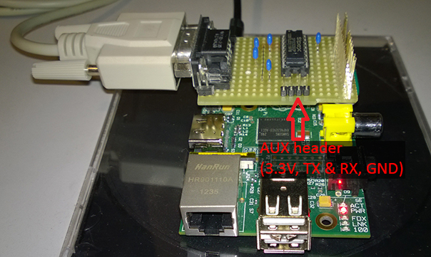
  • In the end, I came out with this solution, made with a MAX3232 compatible IC (the cheaper and more versatile SP3232ECP), some stackable headers, the usual five 100nF capacitors and a DB-9 male connector coming from a scrapped old motherboard.

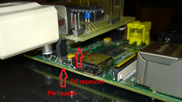
    Serial Port Circuit mounted over a Raspberry Pi B rel. 2

    The P6 header “repeater” (as I call it) also serves to support the circuit on the side of the DB-9 connector.
    A four pin AUX header is also provided for standalone use, with 3.3V, GND, RX and TX connected.
    24 out of 26 GPIO pins are present on the circuit. Of course GPIO pins 8 and 10, TX and RX, are not available for other connections.

    Serial circuit P6 header detail
    Serial circuit AUX header detail

    I’m currently trying the adapter on the Raspberry and seems to be working well. On the PC I’m using an old Prolific USB-to-Serial adapter with a null-modem cable.

    Bye


    Gen 27

    Exactly one month ago I received my Acer Iconia W510, because of a partnership between Acer and Microsoft, which I want to thank both one more time.
    The Iconia W510 features a brand new Intel Atom Z2760 “Clover Trail” SoC with 2 GiB RAM and a 32 GB SSD.
    With a 1366×768 10″ multitouch display and a detachable keyboard it’s one of the first platforms where Windows 8 can show its full potential.
    Following a rather new tradition, the Iconia has been named Harrier and has joined my main pool of computers, composed by Hornet ( my laptop ) and Raptor ( my workstation ).

    I started working on x86 system in 1994 and didn’t have any occasion to work on other platforms until 2008 when I got my first, used, UltraSPARCv9 workstation. I still was a Windows user nevertheless and as such I always had x86 ( and x64 ) systems to run the various version of Windows I used during the last 19 years.

    As a result, I was very interested about the new Windows RT operating system for ARM SoCs.
    I had the opportunity to try it and, even with the limitation of not being able to install any desktop application, there is still a desktop, there are still both command prompt and PowerShell that can run with administrative privileges, there are the usual command line utilities like netsh and a lot of other things which make Windows RT a “complete” operating system.
    Not to mention Windows RT comes with Office H&S 2013.

    Windows on x86 hardware nonetheless is another story, especially if you are a Power User like me.
    For instance, this is my home’s wokspace. The W510 fits nicely on the left of Raptor‘s main screen.

    My desk with two PCs and the Iconia W510

    Being able to run the full range of 32 bit applications for Windows in the world is priceless. There are scenarios where the need to install software like PuTTY or OpenVPN, for instance on UNIX or *nix-based workplaces, overcome the capabilities of any Windows RT device.
    I installed Visual Studio on my Iconia last week and now I’m able to do much of the work I already do on my laptop or my workstation. Of course I can’t run the WP8 emulator, but I can still write down some ideas into code anywhere I am ( with the help of Visual Studio’s IntelliSense ).

    One thing that was really unexpected is the battery life. It’s amazing. I can use it for two whole days without the need of charging the two batteries ( one in the unit, one in the detachable keyboard ).
    I was really surprised, considering that my dad’s Intel Atom based netbook, running Windows 7, could at least last 6 to 7 hours, maybe 8 with an aggressive energy-saving policy.
    The idea to put another battery pack in the keyboard was excellent. When using the Iconia with the keyboard, or while using the keyboard as a stand, the internal battery will be depleted last, when there’s no more charge in the keyboard’s battery.

    The screen is large enough to be used for productivity tasks while, having a 16:9 A/R, it’s little less suited for reading fixed A4 documents. On the other end is comfortable enough to read e-books or other contents with a variable layout, better suited for portrait orientation on a 16:9 screen.
    The minimum screen brightness is low enough to not strain your eyes while reading. BTW, if reading during nighttime without any other light source, it’s better to switch to a white on black, or even a grey on black color scheme if the app / website allow this.

    Design’s fairly good, a little scratch-prone IMHO. I would have put a regular USB port on the side of the unit instead of a microUSB one. The keyboard has another USB port so there is a total of two ports.
    A male microUSB to female USB-A dongle is bundled with the device, so this isn’t a big issue, but personally I hate dongles since time of PCMCIA network card ( because there’s some magic around them that make them disappear sooner or later ).

    The embedded NFC and Bluetooth could be a good option to attach a mouse without sacrificing one of the two precious USB ports, while BitLocker can use the integrated TPM module to securely encrypt data.

    The really big drawback of the unit Acer sent me are the only 32 GB of internal storage that leave really little space for documents and personal data once App and other software ( like Visual Studio Express or Office standard ) start being installed.
    There is a microSD slot that accept cards up to 32 GB ( 64 GB cards are unsupported  ), so data, music, pictures, etc. can be stored there.

    I had some stability issues during the first week that were greatly reduced with the following driver updates.
    I haven’t had one since the last driver update of January 13.

    Overall, being my first tablet, I’m pretty satisfied of it. Of course I have different needs from standard users. I wouldn’t have cared if the Iconia would have weighted 1 lbs more or would have been 1/4″ ticker but maybe having a mSATA SSD instead of the one soldered on the mainboard.

    In the end, I think the Acer Iconia W510 is a very good product, because before being a tablet, is a PC.
    That means, when choosing a tablet, that the Iconia ( as well as the other “Clover Trail” based tablets ) has no restrictions on any App’s store or market, can be fully integrated in a business / enterprise environment when running Windows 8 Pro ( like mine ) and can be connected to any device with available drivers for Windows 8 / 7 or Vista.

    Many friends of mine are starting to consider this product a good balance between a high-end netbook and a mid-range tablet. Of course high-end x86 tablets offer more, but with an higher price. Acer itself produces the Iconia W700 which belong to another class of products.
    After a single month some things start to be addictive: this a sign that the product is good!

    Again, many thanks to Microsoft Italy and Acer Italy for this amazing Iconia W510.

    Bye