With the arrival from Hong Kong of the last adapter, I was finally able to finish my upgrade!
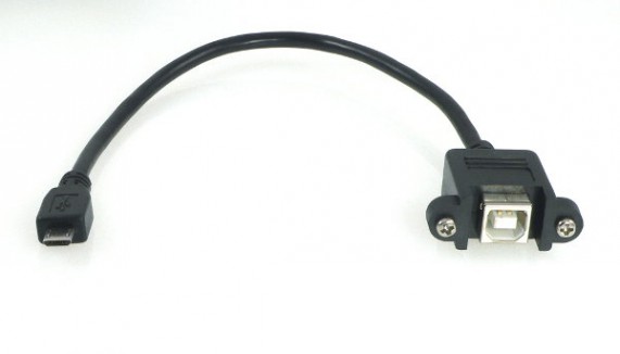
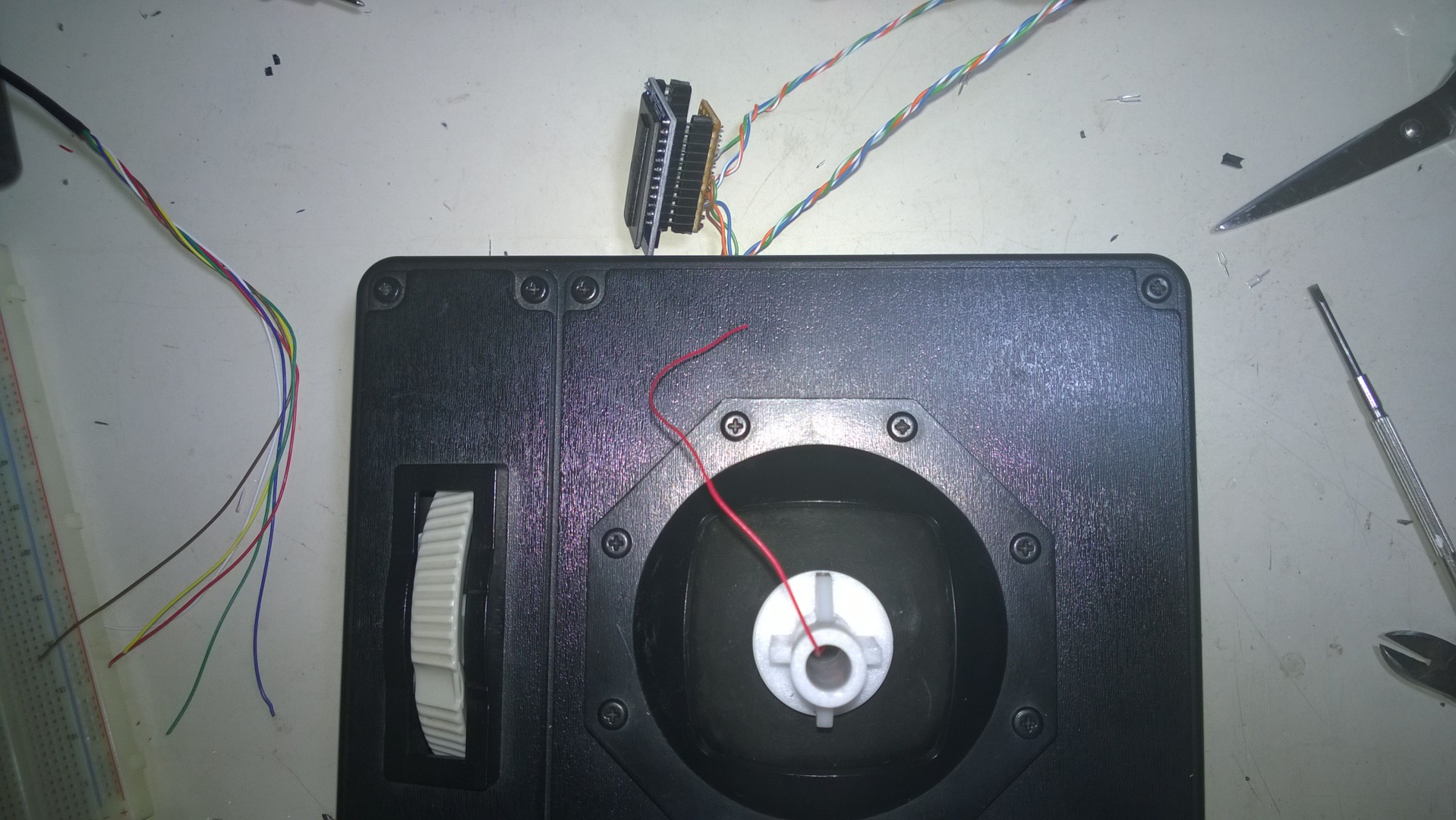
USB B panel mount connector
I enlarged the hole for the original cable and mounted there the panel connector. I can now use whatever USB cable (long or short) I like.
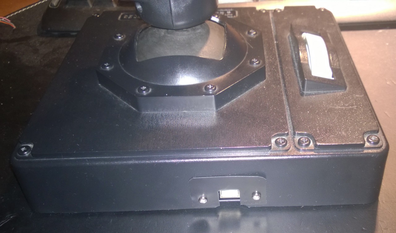
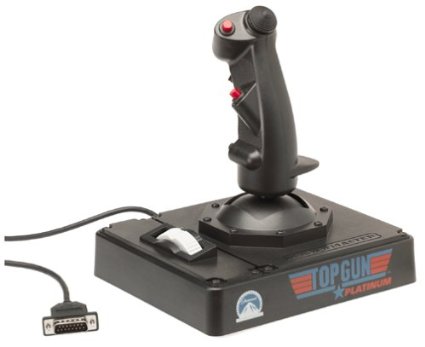
Joystick with USB B port mounted
In the end, this was, after all, a ‘test project’. I’m not gonna use this joystick a lot because… well, I just bought a Thrustmaster Hotas Warthog, and it’s worth every cent I paid.
In conclusion, what I learned from this project?
- When ordering more than one piece of electronic from eBay, especially from Hong Kong, it’s better to try everything when the items arrive, not just when one needs them.
- Without both good gimbals and good springs there is not a good joystick. I did this upgrade because I’m attached to this joystick as it was my first “good” flight controller like 17 years ago and I didn’t want it to stay on the bottom of a box with other useless things. I don’t recommend anyone to buy this joystick with the purpose of upgrading it like I did. Maybe it’s better to buy an FCS Mark II or an X-fighter (better gimbals and better springs if what I read it’s true).
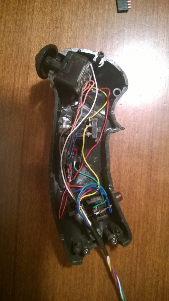
- Cheap pots are cheap (Department of Redundancy Department here). What I mean is that I opted not to upgrade the pots with newer parts or hall sensors, partly because I’m lazy, partly because I think it was completely pointless (gimbals and springs). This means a lot of “garbage” on the analog inputs. Also, this means that the highest and lowest voltage levels change for various reasons (humidity, heat, planetary alignment…).
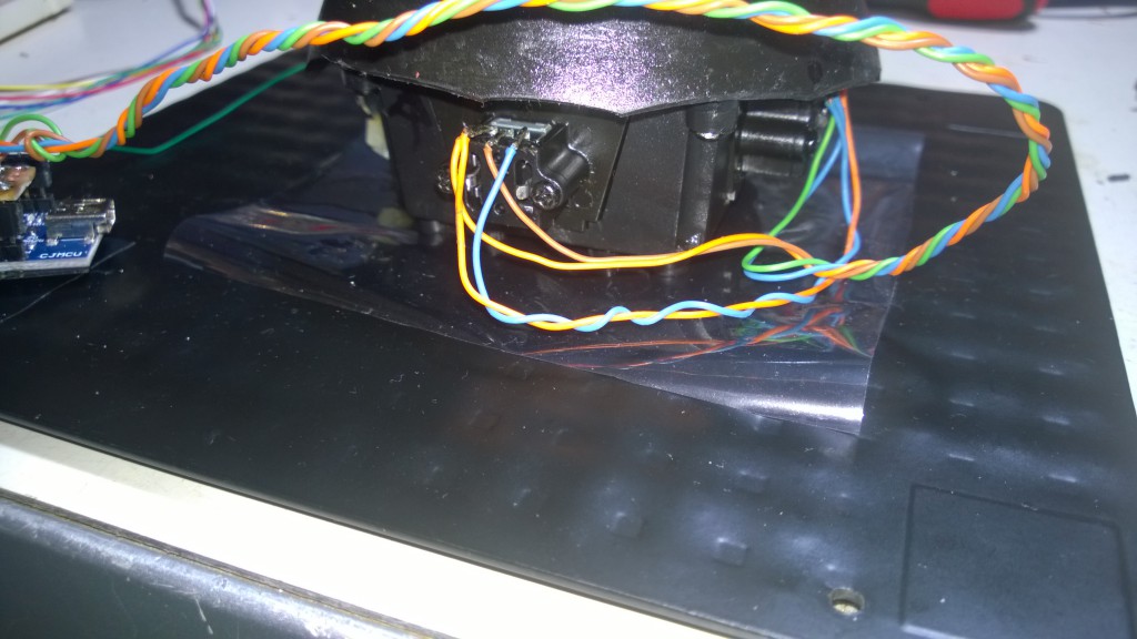
- Flight Simulators are a niche product nowadays but the community is still alive and is doing fine. Cheap $5 Arduino’s clones are extremely versatile. They’re great, really great. Making the electronic parts for a flight controller (sensors excluded) has never been this cheap.
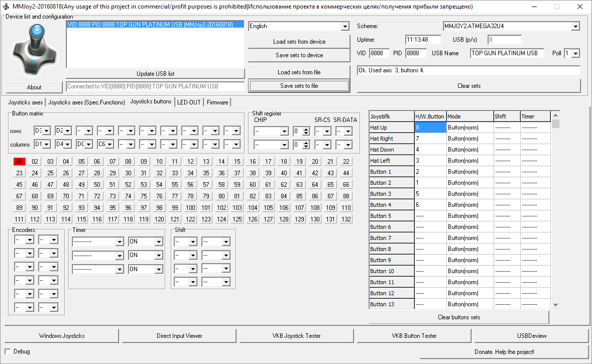
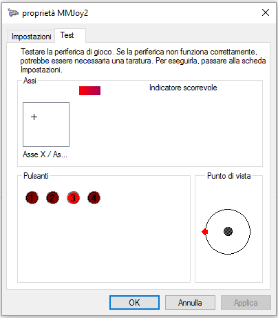
- MMjoy2 is one hell of a software. It’s incredible, does everything, it’s free and open source (hosted on GitHub). I can’t be more grateful to the developer for making this fantastic work.
In the end, my next project will be focused on the same upgrade to a Suncom F-15E Raptor joystick I bought used for €20. I’m also currently looking on eBay for old Thrustmaster TQSs (but the Hotas Cougar throttle it’s more appealing).
After all… it was fun. I’m not gonna use it very much, but I’m fine knowing I did this upgrade.


Commenti disabilitati su Little upgrades to a Thrustmaster Top Gun Platinum joystick – Part 4 of 4